The world of industrial engineering is rich in symbols, used as a universal language for easy and efficient communication. Among this vast array of symbols, valve symbols stand out as an essential category. Valves play a crucial role in controlling the flow of fluids within piping systems, making the understanding of valve symbols an imperative skill for engineers and technicians alike.

What is a Piping & Instrumentation Diagram (P&ID)?
A Piping and Instrumentation Diagram (P&ID) is a comprehensive graphical representation of a process system. It includes details like piping, vessels, control valves, instruments, and process components and equipment. By decoding the valve symbols and other components on a P&ID, one can understand the intricate details of the system and how they all interact with each other, enhancing the ability to design, implement, and troubleshoot the system.
How to Use Piping & Instrumentation Diagram (P&ID)?
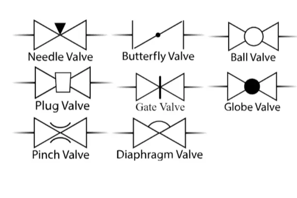
Using a P&ID involves identifying and interpreting the various symbols used. These symbols are standard shapes featuring elements like circles, triangles, lines, or a combination of these. Here, we will focus on valve symbols, depicted typically as two lines (representing piping) connected to a boxy or triangular symbol that represents the valve’s type. Indicators like a vertical line might suggest a gate valve symbol or a small dark circle suggesting a globe valve symbol.
P&IDs vs. PFDs
While P&IDs and Process Flow Diagrams (PFDs) may seem similar, they serve different purposes. PFDs are a high-level representation of the overall process flow, giving an overview of the process. On the other hand, P&IDs provide a detailed depiction of the system, breaking down the process elements like control valves, instruments, pipelines, and connectivity, often utilizing valve diagram symbols to help better understand the design and operation of the system.
Standardization
Standardization plays a crucial role in making P&IDs universally understandable. The International Society of Automation (ISA) has defined strict standards for P&ID symbols, including valve symbols on P&ID diagrams. However, slight variations might exist across different industries and companies; hence, a legend or a key is often provided to explain all symbols used on the diagram in detail.
Valve Symbols
The complex world of process and instrumentation drawings (P&IDs) is replete with a range of valve diagrams and symbols. Chief among these are the 2-way, 3-way, and 4-way valves.

2-Way Valves
The first category of valve symbols featured in P&IDs are 2-way valves. These can be identified by two equilateral triangles pointing towards each other. The purpose of these valves, represented by the likes of ball valve symbol, gate valve symbol, plug valves, and others, is to regulate the fluid flow to prevent backflow. Fundamentally, these valves perform on/off functions and control flow direction. The type of valve is often illustrated by different types of lines, and the flow direction is shown by the arrowhead.
3-Way and 4-Way Valves
Navigating further into the P&ID one can uncover the symbols for 3-way and 4-way valves. These valve symbols visually appear as the 2-way valve symbols, albeit with an additional triangle, indicating an additional pathway for the process media. The 3-way and 4-way valves are often depicted with an L-port or T-port designation to demonstrate the valve’s connection points. Compatibility with more complex networks is an underlying strength of these valve types, enabling fluid to be redirected in multiple directions.
| Valve Type | Usage |
| Gate Valves | Used to isolate or connect flow entirely, not for throttling. |
| Check Valves | Allows flow in one direction only, prevents backflow. |
| Globe Valves | Used for precise regulation of fluid flow. |
| Plug Valves | Used to control flow of liquids and gases. Can be used for isolation as well. |
| Ball Valves | Mainly used for on/off control without pressure drop. |
| Butterfly Valves | Used for regulating or isolating flow, lightweight and smaller footprint in comparison to gate or ball valves. |
| Safety/Relief Valves | Used to protect systems from overpressure situations. |
| Needle Valves | Used in flow metering applications, especially when a constant, calibrated, low flow rate must be maintained for a certain time. |
| Control Valves | Typically motor-operated, they are used to control the rate of flow in a system. |
| Flow Direction Indicators | Used to indicate the direction of flow in a piping system. |
| Diaphragm Valves | Used in applications that require a clean and sterile environment like the pharmaceutical or food industry. |
| Pressure Reducing Valves | Used to reduce a higher inlet pressure to a steady lower downstream pressure. |
Valve Actuators
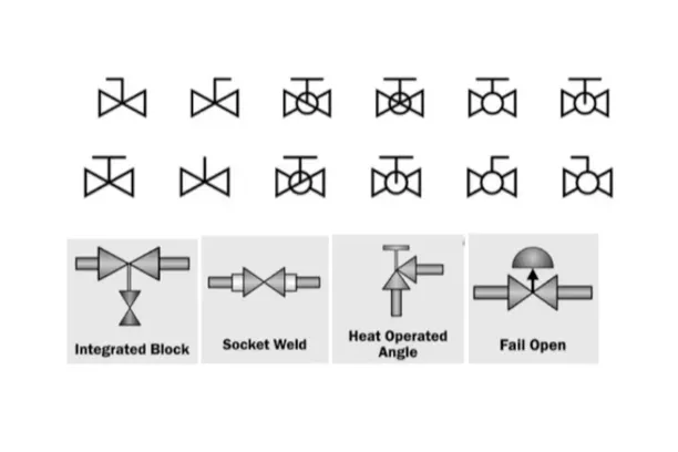
Valve actuators are integral to the operation of valves. The symbol for an actuator is depicted as a line coming from the valve’s center, with a smaller symbol atop the line. In such valve P&ID symbols, electric and hydraulic actuation is represented by letters. For instance, you might notice this in a butterfly valve symbol or a ball valve symbol.
The failsafe position of actuators is indicated by a line and arrow either pointing toward the ball (for failsafe closed) or away from the ball (for failsafe open). These can also be defined with the letters “FO” or FC.”
Valve States: Open, Close, Bistable
Progressing through the complex web of valves, one might determine the state of a valve. Valve states, whether normally open, normally closed, or bistable, play a significant role in process flow control. P&IDs visually represent these as blacked-out valve symbols or use the letters “NC” or “NO”. Bistable valve states mean they retain their position during power loss and require separate action to toggle the state.
End Connections
End Connections link the valve to the process lines. On a piping and instrumentation diagram, these end connections can be depicted as flanged, threaded, weld, or socket weld connections. There are several ways to distinguish these connections using parallel lines, filled and unfilled squares, and circles.
Process Lines
Besides valve symbols and their states, you will come across process lines in P&IDs. Process lines depict the conduits for the process flow and include pipes, tubes, or hoses. They are represented in various styles and are labeled with crucial information such as component’s class, size, and insulation.
Signal Lines
Signal lines, represented by various line symbols in P&ID, illustrate the type of signal—electric, pneumatic, or data—that communicates information between components, instruments, and control system computers.
Equipment
Equipment in P&IDs extends from storage tanks, drums, process vessels, to blowers, fume exhausters, air compressors, and sensors. Each piece of equipment has its unique symbol in the diagram. While it exists in the periphery of valve symbols, it is equally important in understanding the entire piping system.
Tag Numbers
Tag numbers are the generally overlooked aspect of valve symbols. These numbers encapsulate vital aspects of the valve, including properties of the media being measured and its function. Tag numbers provide a means to catalog and maintain the complex array of symbols in P&IDs.
Conclusion
In conclusion, P&IDs offer a comprehensive view of a system’s operation, and understanding valve symbols on P&IDs is a vital skill in the field of process control and engineering. Whether it’s a basic two-way valve or a complex 3-way or 4-way valve, each has its unique symbol, providing insight into the system’s flow control. Mastering these symbols and the way they are represented on the P&ID will prove exceptionally beneficial in designing, operating, and troubleshooting process systems effectively.


