In the complex world of industrial systems, being able to accurately read and interpret diagrams is crucial and among these, the valve diagram holds significant importance. This comprehensive guide aims to equip you with the knowledge to read and interpret valve diagrams, primarily concentrating on their use in process flows and the important symbolism they contain.
How Does a Valve Diagram Help in Understanding Process Flows?
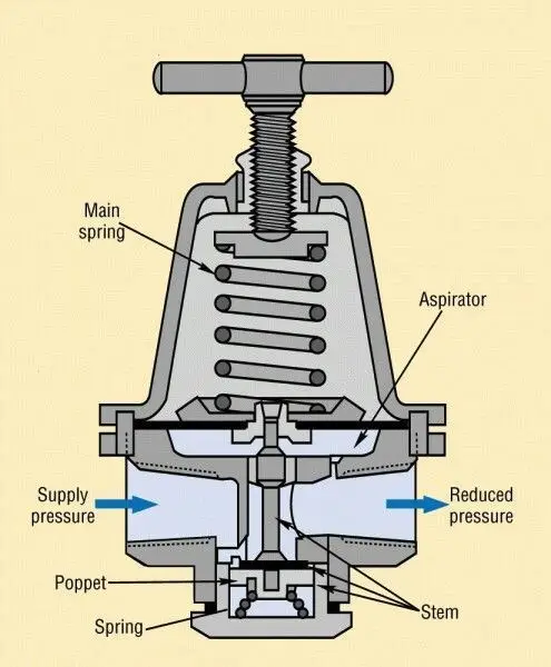
The cornerstone of any process control system is the fluid flow, be it compressed air or any other fluid medium. Valve diagrams, or as they’re referred to in the industrial sector, Piping and Instrumentation Diagrams (P&ID), serve as an effective tool to understand these various process lines and flows. By interpreting a p&id, one can gain insights into how different components like the control valve, gate valve, or check valve interact and contribute to the overall process flow in systems such as air compressors or heat exchangers. Mastering the accurate reading of a valve diagram paves the path to a deeper comprehension of complex fluid dynamics happening within your plant or your process lines.

The relationship between piping and instrumentation diagram and valve diagrams isn’t separate but intertwined. P&ID embeds the use of valve and process flow diagrams, enhancing the understanding of process flows. Valve diagrams, therefore, play a significant role in interpreting P&IDs by denoting the type of valves used, their operation, inlet, center position, and functional process flow graphics diagram.
How to Read Valve Symbols and P&ID Diagrams?
Reading piping and instrumentation diagrams (P&ID) and interpreting valve symbols is a critical skill in fields like engineering and industrial plant management. Here is a guide on how to do that:
Understand What a P&ID Is
A piping and instrumentation diagram is a detailed graphical representation of an industrial process plant. This diagram comprises various components, including control valves, tanks, vessels, piping, and instrumentation. However, a P&ID is not to scale; instead, it highlights the various process equipment and instrumentation diagrams the relationships between these components.

Familiarize yourself with Basic Symbols
Before reading a P&ID, you must first acquaint yourself with the basic symbols used, such as valves, connectors, welding, and lines representing pipes. This enables you to understand the layout of the piping and instrumentation diagram the process including where valves and major equipment are located, and the flow direction in the plant.
Valve Symbols
Understanding valve symbols is equally crucial since these symbols indicate the type of valve, its operation, and control mechanism. Each type of valve has a unique symbol.
Inspect the Process Flow
Arrows will indicate the process flow direction in a P&ID. Following the arrows will guide you to understand the process and instrumentation diagram and how the process moves from one stage to another, and how the valves function in controlling this flow.
Look at Annotations
Annotations provide additional information about components on the diagram. They can tell you details about a valve or component’s class, size, material, flange class, etc.
Valve Actuators
Valves could be manually operated valves, either manually-operated valves or automatically valves. An automatic valve will typically have an additional symbol or note indicating the form of actuation like pneumatic actuation, electric motor actuation, hydraulic actuation, etc.
| Types of Actuators | Applications |
| Manual Actuators | small-sized valves where the flow of fluid doesn’t require frequent regulation |
| Electric Actuators | industrial applications (water and wastewater treatment plants, oil and gas pipelines)automation of industrial process control |
| Pneumatic Actuators | oil and gas industrychemical plants, HVAC systems, and power plants |
| Hydraulic Actuators | heavy-duty applications (hydraulic oil and gas industry)where high force and robust control are required |
| Solenoid Actuators | shut-off valve operation, pump controlfluid power pneumatic and hydraulic systems |
| Electro-Hydraulic Actuators | marine, offshore, pipelines, and the process industry |
| Piezoelectric Actuators | microelectronics production, semiconductor technology, and medical engineering |
With practice and repeated exposure to various P&IDs and valve diagrams, interpreting them becomes second nature, and a valuable skillset in many technical fields.
What Are the Types&Usages of Valve Diagrams?
Distinguishing the difference of valve symbols such as butterfly valve symbols, ball valve symbols, gate valve symbol or check valve symbols can be the deal-breaker when it comes to accurately interpreting valve diagrams. Each valve symbol on these diagrams reveals crucial information about the component, from its function to its operational state. Among them, the number of ports of 2-way valves, 3-way valves, and 4-way valves are different.
| Types | Usages |
| 2-Way Valves | 2-way valves, also known as on-off valves or shut-off valves, regulate the fluid flow by allowing or blocking it completely. They are commonly used in simple on-off applications where the flow needs to be started or stopped. |
| 3-Way Valves | 3-way valves have three ports and can redirect fluid flow between two different paths. They are crucial for applications that require the fluid to be directed to either of the two outlets or through both simultaneously. These valves are commonly used in systems that need diverting, mixing, or bypass capabilities. |
| 4-Way Valves | 4-way valves have four ports and are primarily used in applications where multiple actuators, such as cylinders or motors, need to be controlled simultaneously. These valves provide the ability to switch between different actuator positions or control the direction of both inlet and outlet flows. |
| Gate Valves | The symbol features a front gate valve-like valve plate that moves up and down to control the flow of fluid through piping system. Gate valves are primarily utilized as shut-off valves in pipeline systems, allowing or preventing the flow of the medium. |
| Check Valves | Check valves are designed to allow fluid to flow in one direction only, preventing backflow. They are commonly used in several industries like water, wastewater, and stormwater pumping applications, and any system where backflow could potentially cause damage. |
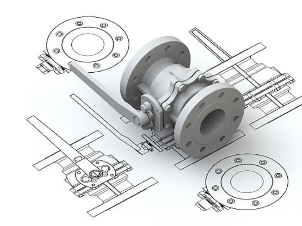
| Ball Valves | The spherical disc, or the ‘ball’ in the middle, controls the medium flow. Ball valves are well-suited for applications where the flow needs to be completely shut-off. |
| Butterfly Valves | Butterfly valves are used to regulate, throttle, and stop the flow and find use in water supply, wastewater treatment, fire protection, and industrial applications. |
| Globe Valves | Works when the valve plug stretches up and down to achieve a seal within the valve. Globe valves provide more precise flow control and regulation. |
| Plug Valves | Plug valves are suitable for on-off flow control valves because of flow and applications involving high temperature and pressure. In a plug valve, a plug with a hole rotates to allow fluid to pass through pinch valve or the valve to be blocked. |
| Solenoid Valves | Solenoid valves are usually electromechanical devices that control the flow of fluid or gas by means of an electric current. |
| Relief Valves | A relief valve symbol represents a relief or safety valve designed to release excess pressure from a system. Most commonly used in high-pressure systems, these safety valves open when a certain pressure level is attained, thereby less pressure fans safeguarding systems from overpressure damage. |
| Check-stop Valves | They maintain the unidirectional flow of fluids (check valve functionality) and can also stop the flow completely when the flow process is needed (stop valve functionality). They are often used in water supply and compressed air systems. |
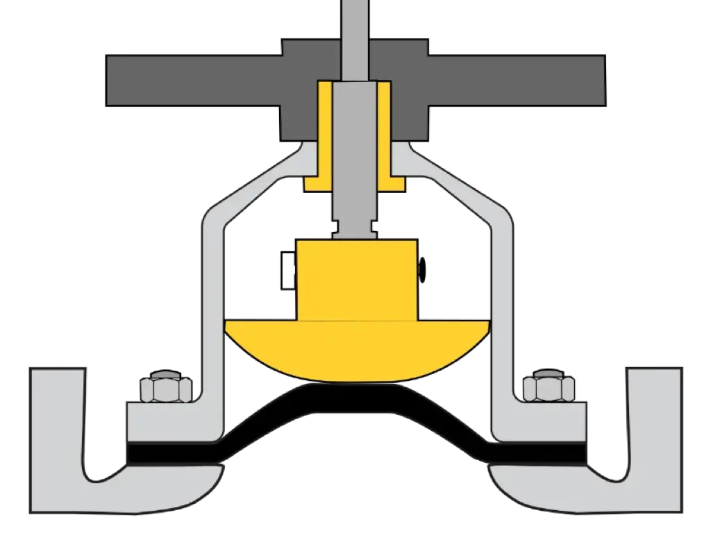
| Diaphragm Valves | A diaphragm valve symbol in a valve diagram signifies the valve’s unique construction. The valve actuates by applying a force to compress the diaphragm against a saddle or seat. Diaphragm valves are typically used in process applications that require the robust control of liquids and gases. |
| Angle Valves | The angle valve symbol depicts an angle valve that alters the direction of fluid flow by 90 degrees. Because of its angled design, an angle valve can also provide certain flow control capabilities and is used primarily in gas and liquid services. |
| Block and Bleed Valves | The block valve isolates media flow from the downstream process, and the bleed valve vents the trapped process fluid safely to a vent recovery system. They are used in hydraulic and pneumatic systems to drain out liquids for maintenance or to depressurize the system. |
| Needle Valves | Needle valves are used for precise flow control in systems where fine adjustments are required. They feature a slender, tapered needle-like stem that fits into a seat, allowing for precise regulation of fluid flow by raising or lowering the stem. They are ideal for applications where precise control is necessary, such as in laboratories, fuel and gas control systems, or any situation requiring fine-tuned regulation of flow. |
What are the Safety Implications of Correctly Interpreting Valve Diagrams?
The correct interpretation of valve diagrams instrument symbols is critical in maintaining the safety of plant operations. It allows operators to identify the types of valves used, their functional states, and their interconnections within the process. For example, recognizing a pressure relief valve symbol may save the system from potential overpressure scenarios, ensuring overall plant safety.

Conclusion
In the intricate world of industrial plant systems, understanding valve diagrams is a vital skill for anyone involved in the process. Whether you are a seasoned engineer or new to the field, this comprehensive guide will be helpful in interpreting everything from a globe valve symbol to a hydraulic valve operation.
If you want to know more, you can contact Dombor. By mastering the valve diagrams, you will have a pivotal tool at your disposal that can ensure safety, improve efficiency, and ensure you are capable of discussing and improving processes with the rest of your team. Maintenance, safety checks, process tweaks – all these operations benefit enormously from a sound understanding of valve diagrams.


