What are P&ID Symbols?
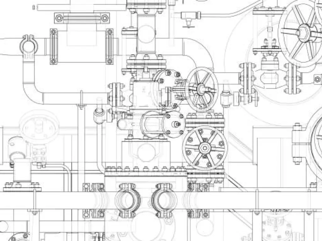
P&ID symbols, also known as piping and instrumentation diagram symbols, are graphical representations of the various components that make up a process system, such as equipment, instruments, piping, valves, and others. These standardized symbols play a crucial role in helping industry professionals like engineers, technicians, and operators understand and communicate project design and process information accurately and consistently. Incorporating P&ID symbols into your work is essential to ensuring accuracy and efficiency in process management.

About P&ID Symbols: Their Meanings and Usages
P&ID symbols are used to convey specific information about the components within a process system. Each symbol type has particular meanings within the context of an industry-standard notational system. The symbols fall into various categories, including p&ID equipment symbols, piping symbols, pump symbols, valve symbols, vessel symbols, instrumentation symbols, and others. These categories often have subcategories that encompass a wide range of specific symbol designs.
| Category | Symbol | Meaning | Usage |
| P&ID Equipment Symbols | Various symbols representing different types | Mechanical equipment, process devices, and other hardware components | Depict equipment or device locations in a process |
| Piping P&ID Symbols | Lines, elbows, reducers, flanges, etc. | Fluid transportation and connections in process systems | Represent piping pathways and flow direction |
| Pump P&ID Symbols | Centrifugal, gear, sump, vacuum, screw, etc. | Different types of pumps for fluid transportation | Indicate pump locations and types |
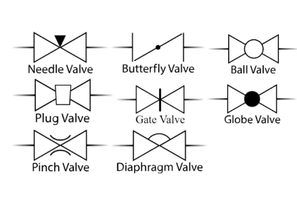
| Valve P&ID Symbols | Gate, check, globe, ball, butterfly, etc. | Regulate, direct, or control the flow of fluids in process systems | Show valve locations, types, and flow control |
| Vessel P&ID Symbols | Tanks, cylinders, columns, bags, etc. | Containers used to store, process, or transport fluids | Represent vessel locations, shapes, and capacities |
| P&ID Instrumentation Symbols | Sensors, transmitters, meters, etc. | Measurement and control devices for various process parameters | Depict instrument locations and interconnections |
| Heat Exchangers P&ID Symbols | Boilers, condensers, etc. | Devices for transferring heat between fluids or surfaces | Indicate heat exchanger locations and types |
| Compressor P&ID Symbols | Axial, reciprocating, rotary, etc. | Devices that compress gases or force air into other objects | Represent compressor locations and types |
| Motor P&ID Symbols | Electric motors, generators, etc. | Power sources for equipment and devices within process systems | Depict motor locations, types, and power sources |
| P&ID Line Symbols | Electrical, pneumatic, data lines, etc. | Signal transmission between equipment, instruments, and components | Represent connections, communication, and signal types |
At the same time, from an English alphabet standpoint, you also need to know most of the time X serves as a “Catch All” for everything that is not normal defined in P&ID’s. Things like Pressure (P), Weight (W), Temperature (T) and Flow (F) are self evident but a X may be many different things depending on the device. That is why it will not be defined on the drawing. Understanding these categories and the meanings attached to their associated symbols is essential for professionals involved in designing, operating, and maintaining process systems.
| P&ID Symbol Abbreviations | Meaning |
| AC | Alarm, Controller |
| AI | Analog Input |
| AO | Analog Output |
| AT | Analytical Transmitter |
| CB | Circuit Breaker |
| CR | Control Relay |
| DI | Digital Input |
| DO | Digital Output |
| FQ | Flow, Totalizer |
| FT | Flow, Transmitter |
| FS | Flow, Switch |
| FT | Flow, Transmitter |
| HS | Hand Switch |
| JIC | Joint Industry Council |
| LS | Level Switch |
| LT | Level Transmitter |
| PC | Pressure Controller |
| PD | Pressure Differential |
| PI | Pressure Indicator |
| PS | Pressure Switch |
| PT | Pressure Transmitter |
| PHT | pH Transmitter |
| PTC | Pressure Transmitter/Controller |
| TC | Temperature Controller |
| TE | Temperature Element |
| TI | Temperature Indicator |
| TS | Temperature Switch |
| TT | Temperature Transmitter |
| V | Valve |
| XI/XO | Software Input/Output |
P&ID Equipment Symbols
Equipment symbols in P&ID diagrams represent various pieces of hardware used in the process system. These can include compressors, conveyors, turbines, vacuum pumps, motors, heat exchangers, and other mechanical devices. Each type of equipment has its corresponding symbol that provides a visual representation of the equipment to be used within the system.
Piping P&ID Symbols
Piping P&ID symbols represent the various components involved in the transportation of fluids within a process system. These can include pipes, fittings, flanges, reducers, coupling, and other fluid transport devices. The piping symbols help engineers and technicians understand and depict the functional relationships between the piping components in a process system.
Pump P&ID Symbols
Pump symbols in P&ID diagrams are used to represent different types of pumps used in process systems, such as centrifugal pumps, gear pumps, sump pumps, vacuum pumps, and screw pumps. Understanding pump symbols is essential since they provide crucial information on the functionalities of various pumps, their connections, and the direction of fluid flow within the system.
Valve P&ID Symbols
Valves are crucial components in process systems that regulate, direct, or control the flow of fluids. Valve P&ID symbols help convey information about the types and functionalities of valves in a system. Some common valve symbols include those for gate valves, check valves, globe valves, ball valves, and butterfly valves. In Europe, valve symbols may vary slightly based on regional preferences or coding conventions. These symbols are essential for depicting the precise locations, types, and functionality of valves in a process system.
Vessel P&ID Symbols
Vessel symbols represent various types of containers used to store fluids in a process system. Vessel symbols include those for tanks, cylinders, columns, bags, and others. These symbols help engineers and technicians understand the capacities, shapes, and properties of different containers within a system.
P&ID Instrumentation Symbols
Instrumentation symbols in P&ID diagrams represent devices that measure and control various parameters within a process system, such as flow, temperature, pressure, and angle. The instrumentation symbols include meters, transmitters, sensors, indicators, and other types of measurement and control devices.
Heat Exchangers P&ID Symbols
Heat exchangers are devices used to transfer heat energy between different surfaces, fluids, or areas within a process system. Heat exchanger P&ID symbols represent equipment like boilers, condensers, and other heat transfer devices.
Compressor P&ID Symbols
Compressor symbols in P&ID diagrams represent devices that compress gases or force air into other objects. These symbols include those for axial compressors, reciprocating compressors, rotary compressors, and other types of compressors used in process systems.
Motor P&ID Symbols
Motor symbols in P&ID diagrams represent devices that drive or power various types of equipment in process systems. Motor symbols typically include those for electric motors, generators, and other types of power sources.
P&ID Line Symbols
Line symbols in P&ID diagrams show how signals are transmitted between equipment, instruments, and other components within a process system. These symbols indicate the type of signal being used, such as electrical, pneumatic, or data connections.
International Standards and Guidelines for P&ID Symbols
Numerous international standards and guidelines dictate the correct usage of P&ID symbols in the process industry. The American National Standards Institute (ANSI) and the International Society of Automation (ISA), among others, provide essential reference points for standardized P&ID notation. Adherence to these standards ensures effective and comprehensible communication between project teams, suppliers, and other stakeholders, similar to ensuring a shared ‘alphabet’ in a written language. Email-based communication and collaboration platforms can also greatly aid in maintaining consistency and accessibility of P&ID standards among teams.
Common Challenges and Solutions in Implementing P&ID Symbols
The implementation of P&ID symbols in the process industry faces a few common challenges. These include ensuring consistency and understanding among team members, keeping abreast of industry standards, and staying updated with technological advancements. Solutions like regular training, creating organizational guidelines, and making use of collaborative software tools can help address these issues. Like using an updated ‘dictionary’ list, staying updated with P&ID symbols and their latest meanings can be instrumental in improving process system designs.
Tips for Using P&ID Symbols
- Choose symbols according to industry standards to ensure compatibility and understandability across teams and stakeholders.
- Use clear, concise labels and annotations for each symbol to provide additional information and context.
- Maintain proper symbol size, proportion, and spacing for easy readability and to avoid clutter on the diagram.
- Use layers in your P&ID diagrams, separating them by categories such as equipment, piping, instrumentation, or electrical, to enhance organization and accessibility.

- Regularly update P&ID diagrams to reflect changes in system components, equipment upgrades, or process modifications.
- Utilize software with built-in P&ID symbol libraries and templates to streamline the design process and improve consistency.
- Incorporate document control procedures and version tracking to ensure that the most updated P&ID diagrams are available for team members and stakeholders.
Conclusion
As technology continues to advance and industry requirements evolve, P&ID symbols and their usage will likely undergo changes to adapt to new systems, processes, and equipment. Emerging trends may include the increased use of intelligent P&ID symbols, which can provide real-time data and analysis for improved decision making, and the integration of P&ID symbols with other software applications for enhanced collaboration and efficiency. By staying updated on advancements in P&ID symbol usage and incorporating them into their work, professionals can better meet the needs of today’s ever-changing process industry landscape.


